| ·It is a single-line lidar based on dTOF ranging principle. ·It has the advantages of small size, simple use and high cost performance. ·Suitable for navigation, obstacle avoidance and diversification of regional monitoring scenes. |
| ▊ | Product specification |
product model | Maximum detection range | Detection accuracy | Scanning angle | output form |
NJ501-1570CP | 15m@70% reflectivity | ±4mm@1sigma | 270° | PNP |
NJ501-1570CN | 15m@70% reflectivity | ±4mm@1sigma | 270° | NPN |
NJ501-2570CP | 25m@70% reflectivity | ±4mm@1sigma | 270° | PNP |
NJ501-2570CN | 25m@70% reflectivity | ±4mm@1sigma | 270° | NPN |
NJ501-2570HP | 25m@70% reflectivity | ±4mm@1sigma | 270° | PNP |
NJ501-2570HN | 25m@70% reflectivity | ±4mm@1sigma | 270° | NPN |
NJ501-3570HP | 35m@70% reflectivity | ±4mm@1sigma | 270° | PNP |
NJ501-3570HN | 35m@70% reflectivity | ±4mm@1sigma | 270° | NPN |
NJ501-4070HP | 40m@70% reflectivity | ±4mm@1sigma | 270° | PNP |
NJ501-4070HN | 40m@70% reflectivity | ±4mm@1sigma | 270° | NPN |
Installation mode | Horizontal installation mode (SZ), vertical installation mode (CZ) and protective cover installation mode (FZ) | |||
Power cord | The standard is 1m, and the length of 5m can be selected. | |||
Programming line | Standard gift | |||
explain | The difference between NJ500 obstacle avoidance scanner C series and H series lies in: 1. The angular resolution of C series is: 0.3°@30HZ by default, and 0.3 @ 20/25/30hz/40hz is supported; The angular resolution of H series is: 0.3°@30HZ by default, and 0.3 @ 20/25/30hz/40/50hz is supported; In contrast, the H series has an extra 50Hz motor speed. 2. The response time of H series can be faster by scanning the same data. 3. At the same time, the display refresh rate of objects around H series is higher. | |||
Laser scanner main body | Power cord | Programming line |
|
|
|
▊technical parameter
Angular resolution
Measuring parameter | ||
Ranging radius | 15m@70% reflectivity /25m@70% reflectivity /35m@70% reflectivity /40m@70% reflectivity | |
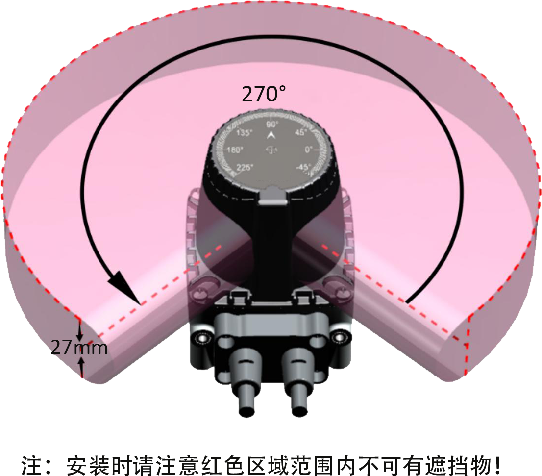
Scanning range angle | 270° | |
Angular resolution | The default value is 0.3°@30HZ, and it supports 0.3 @ 20/25/30hz/40Hz/50Hz (NJ 500 obstacle avoidance scanner C series supports 40hz at the highest and H series supports 50hz at the highest). | |
Distance deviation | ±2cm(Typical) ① | |
repeatability | ±4mm@1sigma② | |
Scanning plane angle | Pitch 0.5; Roll 0.5 | |
Electrical/mechanical parameters | ||
operating voltage | DC9~28V | |
Power-on start time | Typical value 10s | |
power consumption | < 2w (no load at output) | |
output | PNP/NPN available (default PNP) | |
outline dimension | 52mm×52mm×70mm | |
Cable length | standard 1m | |
ambient temperature | Work:-10℃ ~ 50℃ (no frost and fog in the window); Storage:-40℃ ~ 70℃ | |
ambient humidity | Work: 35% RH ~ 85% RH; Storage: 35% RH ~ 95% RH | |
Anti-light interference | 80000Lux | |
resist the impact | Acceleration 10g;; Pulse duration: 16ms | |
Collision times: three axes, each axis is 1000 10 times. | ||
Vibration resistance | Frequency 10 Hz ~ 55 Hz; Amplitude: 0.35±0.05mm | |
Scanning times: 20 times for each of XYZ three axes. | ||
the protection grades | IP65 | |
Electromagnetic compatibility (EMC) | EMI | EN61326-1:2013 |
EN55011:2009+A1:2010 | ||
EMS | EN61326-1:2013 | |
EN61000-4-2:2009 | ||
EN61000-4-3:2006+A1:2009+A2:2010 | ||
EN61000-4-4:2004+A1:2010 | ||
EN61000-4-6:2014 | ||
EN61000-4-8:2010 | ||
Configurable function | ||
Sector configuration | Users can configure YB's protection zone into the required shape through configuration software. | |
Response time | 67ms(2 scans) ~ ~536ms(16 scans), and the default is 67ms. | |
Zone group switching | Four groups of external input signals (INPUT1, INPUT2, INPUT3, INPUT4) realize the switching of 16 regional groups. | |
Note:
1. The measurement error of materials with different reflectivity is controlled within 2cm (typical value). The ex-factory test method: Three kinds of test pieces (black flannel, white paper and reflective sticker) are placed at different angles and the same distance (59cm) on the whole machine inspection automation fixture. The deviation between the central value of each material and the real distance is within 2 cm, and the maximum difference between the three materials is within 2 cm.
2. 10% black velvet 600mm position measurement statistics.
▊Schematic diagram of working principle and protection area configuration
Schematic diagram of protection area 1 | Schematic diagram of protection area 2 |
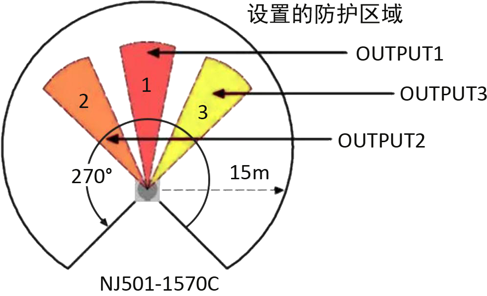 |  |
sign | meaning | describe |
1 | Protected area 1 | OUTPUT1 enters the OFF state when an obstacle is detected. |
2 | Protected area 2 | OUTPUT2 enters the OFF state when an obstacle is detected. |
3 | Protected area 3 | OUTPUT3 enters the OFF state when an obstacle is detected. |
Note:
1. The measurement error of materials with different reflectivity is controlled within 2cm (typical value). The ex-factory test method: Three kinds of test pieces (black flannel, white paper and reflective sticker) are placed at different angles and the same distance (59cm) on the whole machine inspection automation fixture. The deviation between the central value of each material and the real distance is within 2 cm, and the maximum difference between the three materials is within 2 cm.
2. 10% black velvet 600mm position measurement statistics.
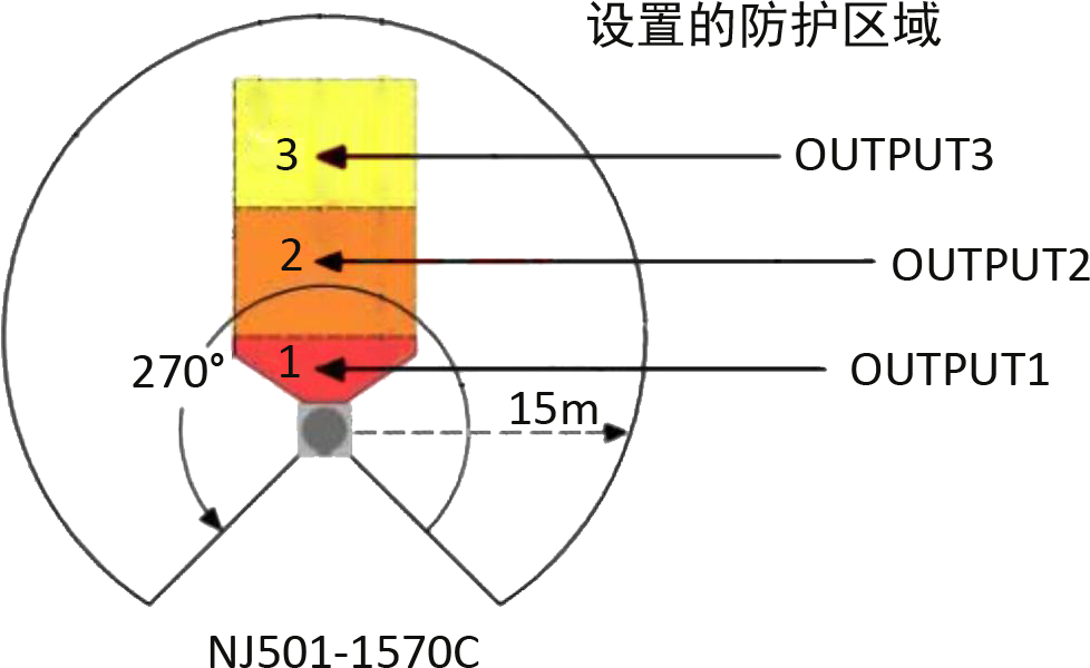
▊Schematic diagram of working principle and protection area configuration
Schematic diagram of protection area 1 | Schematic diagram of protection area 2 |
 |  |
sign | meaning | describe |
1 | Protected area 1 | OUTPUT1 enters the OFF state when an obstacle is detected. |
2 | Protected area 2 | OUTPUT2 enters the OFF state when an obstacle is detected. |
3 | Protected area 3 | OUTPUT3 enters the OFF state when an obstacle is detected. |
▊Indicator light status
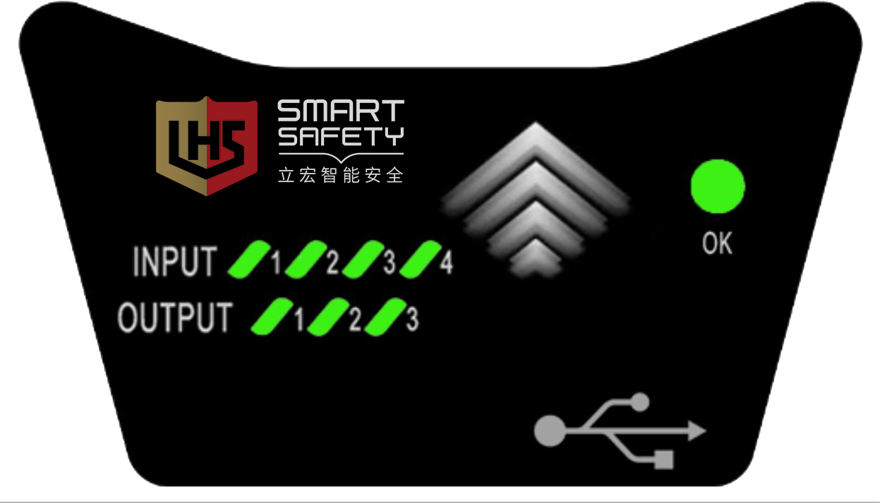 |
OK: After power-on, the trouble-free OK light is always on, and the trouble-free OK light flashes. INPUT(1~4): lit when the input is ON, and turned OFF when the input is OFF. OUTPUT(1~3): lights when there is no obstacle, and turns off when there is an obstacle. Note: When the equipment is just powered on, all the indicator lights will enter the running water state, and the OK light will go out for 10 seconds, indicating that the equipment is starting and is in a normal state. |
▊Cable interface
The configuration cable is a standard USB Type-C data cable (optional). See the figure below for the cable structure, and the standard cable length is 1m. | 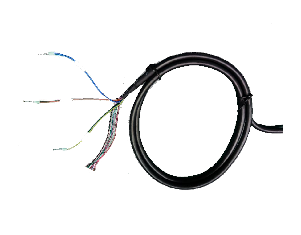 |
colour | signal | describe |
blue | 0V | working power supply |
palm | 24V | |
Yellow/green | PE | |
Red/blue | COM | The common terminal of the regional group switching signal input, when the input signal is PNP logic, COM is connected to 0V; When the input signal is NPN logic, COM is connected to 24V. |
powder | INPUT1 | Regional group selection signal, which can switch between regional groups through the changes of input signals of INPUT1, INPUT2, INPUT3 and INPUT4. |
green | INPUT2 | |
ash | INPUT3 | |
red | INPUT4 | |
black | OUTPUT1 | Three independent PNP(NPN) outputs; PNP transistor output; In the ON state, the load current is ≤100mA and the output voltage is ≥ VCC-2v; In the OFF state, the leakage current is ≤1mA, and the residual voltage is ≤ 1V (excluding the influence of wire extension). When the NPN transistor outputs, the load current is ≤100mA and the output voltage is ≤2V in the ON state; In the OFF state, the leakage current is ≤1mA and the residual voltage is ≤2V (excluding the influence of wire extension). The protectiON area is on when there is no object; In the OFF state when there is an object. |
white | OUTPUT2 | |
purple | OUTPUT3 | |
Ash/powder | OK | Independent PNP(NPN) output, the fault state output is OFF, and it is ON when there is no fault. |
▊Product dimension diagram
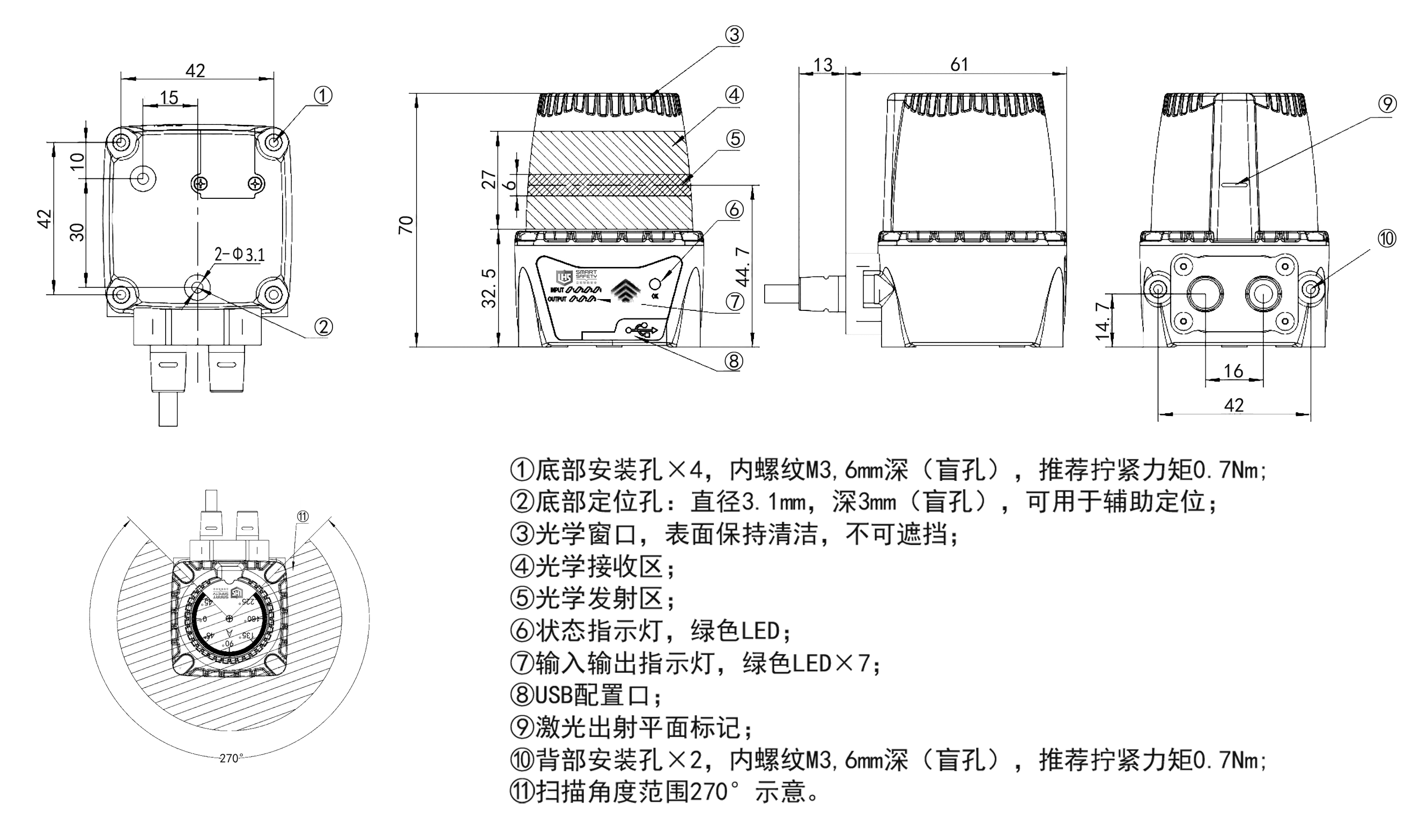
▊Scanning range
▊Installation mode
Horizontal installation mode | |
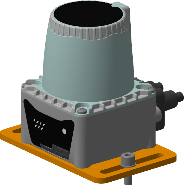 | 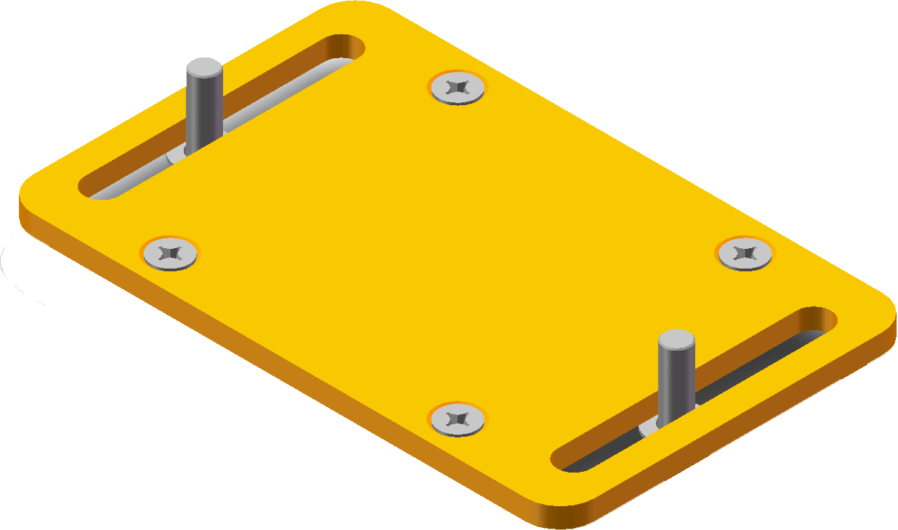 |
Vertical installation mode | |
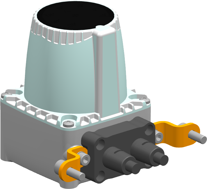 | 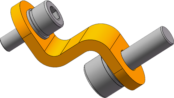 |
Installation mode of protective cover | |
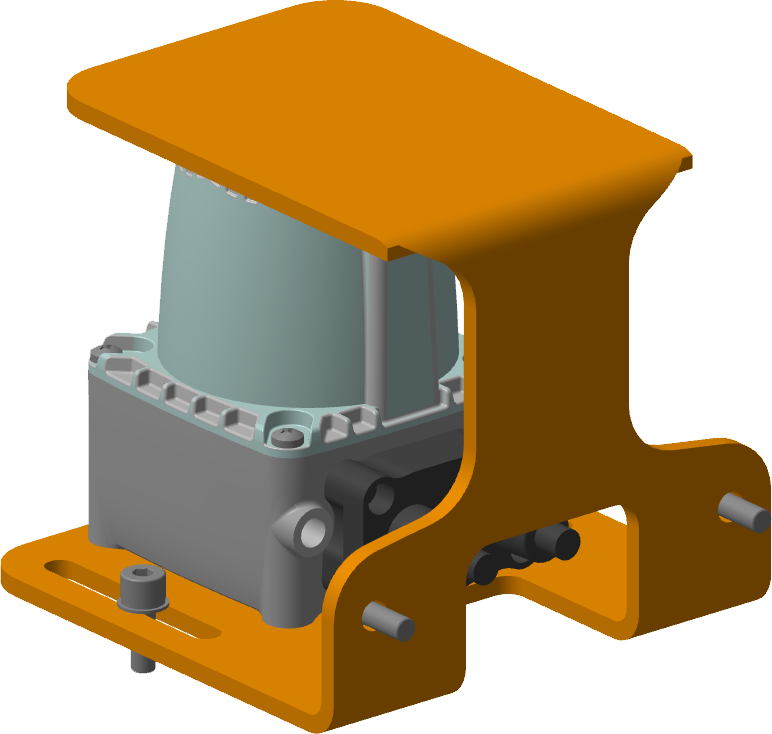 | 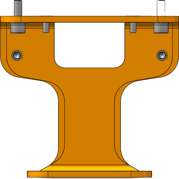 |

Lihong Safety Equipment Engineering (Shanghai) Co., Ltd.
E-Mail: info@lh-safety.com
Address: 581 Xiuchuan Road, Chuansha Town, Pudong New District, Shanghai
(Greenland East Coast International Plaza-Room A 313)
Copyright ? Lihong Safety Equipment Engineering (Shanghai) Co., Ltd. ICP19034341-1 Technical Support: lanjujing
